
The Road to MPLS
This year I’ve build two totally different MPLS Service Provider networks. One network has limited MPLS with VPLS on MikroTik, the other is a full MPLS L3VPN on HPE Comware gear.
Articles in this Series
Normally MPLS is abstracted out on network diagrams as one or more clouds with MPLS written on them. In those networks, it is someone else’s job to run that. This blog series is about operating an MPLS Service Provider cloud from the inside, instead of the usual perspective of using someone else’s MPLS.
- The Road to MPLS
- MPLS Labels Explained
- MPLS L3VPNs
- Providing Layer 2 over MPLS with VPLS
- MPLS and QoS
Experience so far
I set up a lab of various MikroTik routers, and built out a network that was similar to real life. I then proceeded to build a full MPLS L3VPN environment, with P, PE, and CE routers. When I was satisfied, I moved on and changed the lab network into an MPLS VPLS experiment. As it turns out the same topology worked for both.
I found it helpful for my own knowledge to read blogs and KB articles describing how to operate MPLS (on mostly Cisco, but some MikroTik too), and then translating those examples into working MikroTik and Comware lab configurations. This ensured that I had a more vendor-neutral working understanding of each component.
Why?
So why is MPLS so popular in Service Provider networks?
- Latency
- MPLS can lower latency on a network because a routing/FIB lookup is not needed at each hop along the way. Labels get stacked up when the packet is encapsulated into a MPLS frame, and routers remove labels instead of looking at the packet’s layer 3 headers.
- QoS
- Again because of the way that MPLS works, QoS bits get written to a MPLS label once when the packet is encapsulated into MPLS, and can be read easily along the wire without needing to look at packet header contents at each hop.
- Ease of Management & Abstraction
- To provide a layer 2 or layer 3 circuit between A and Z, only A and Z actually need to be touched (the PE routers), nothing in between needs to be plumbed into the network (VLANs, IP routed paths, etc). The MPLS backbone can also be operated by a different team from the one(s) that do L3VPNs, and Layer 2 circuits.
- Industry Standard
- MPLS is standards based, and has broad vendor support. This prevents vendor lock in, and allows you to run a network on more than one vendor if you should choose.
How?
How is MPLS done?
- Routed Backbone
- A underlaying routed network (often called the backbone), using an IGP routing protocol like OSPF.
- Config
- Layer 2 and MPLS MTUs are configured to accomodate the MPLS labels and encapsulation.
- LDP
- LDP, the Label Distribution Protocol is configured, and run to distribute labels between routers.
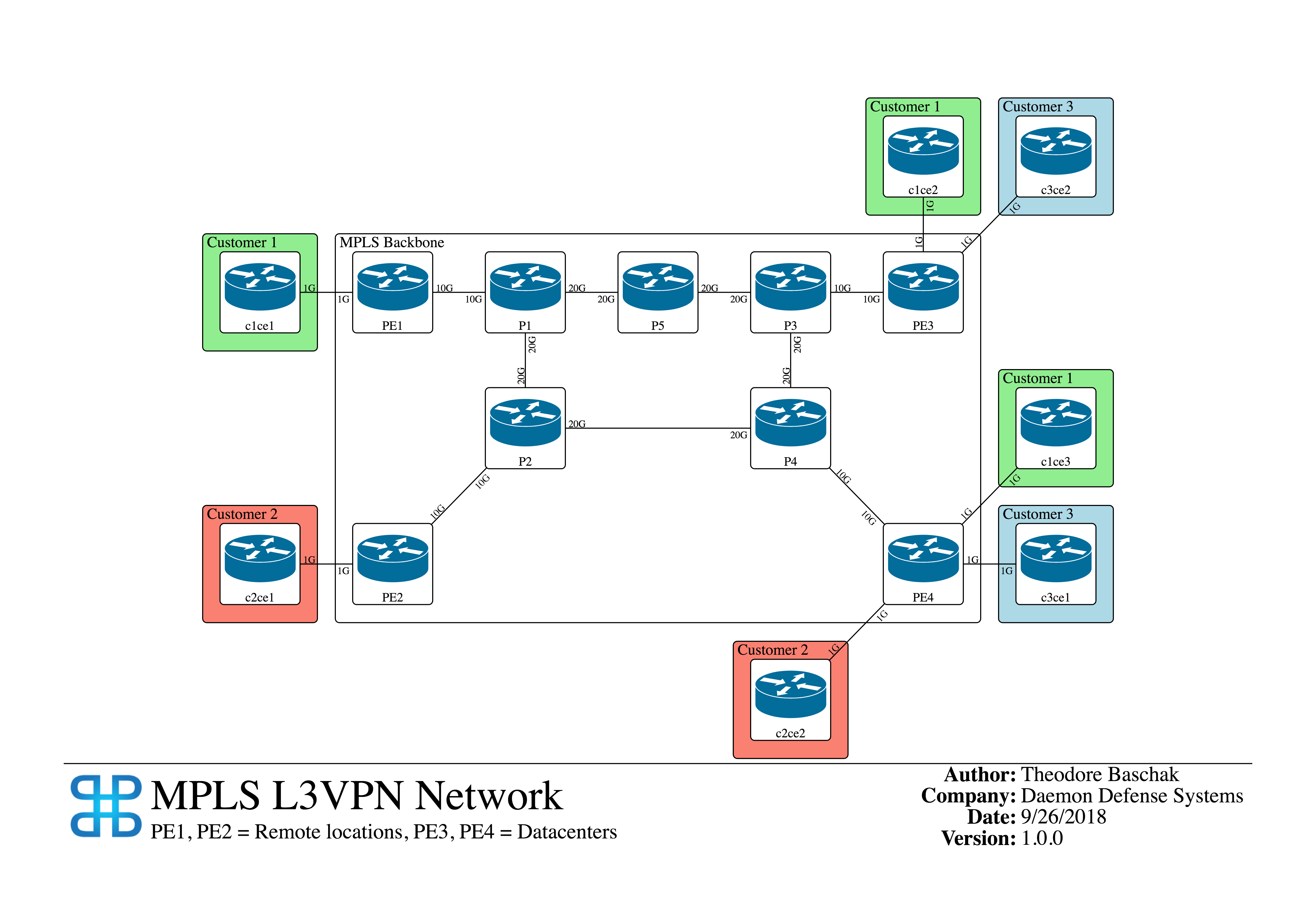
- L3VPN
- L3VPN offers customers routed access to their own MPLS Cloud/VRF with CE-PE peering. Customers can insert their own routes with their own chosen (private) ASNs at various locations and have it all glued together with MPLS. This can be used for branch to branch, branch to datacenter or cloud, or some combination of all. On the Service Provider side this is all glued together between PE devices with vpnv4 BGP peering.
- VPLS
- With VPLS, LDP is configured to advertise labels for backbone loopbacks used for VPLS. Routed traffic on the network is not label-switched over MPLS. VPLS layer 2 tunnels are plumbed between loopbacks with an optional extended community to identify that tunnel uniquely.
Useful Resources
Aside from Cisco and HPE product documentation, I found the following resources useful in my learning journey.
- PacketLife.net: Creating an MPLS VPN - zero to MPLS L3VPN in 15 minutes or less.
- PacketLife.net: Route Distinguishers and Route Targets - what are these 65000:xx import/exports?
- PacketLife.net: VRF Export Maps - applying RD’s and RT’s.
- PacketLife.net: MPLS cheat sheet
- MikroTik Wiki: Maximum MTU on RouterBoards - useful diagrams of what packets look like on the wire.
- MikroTik Wiki: MPLS VPLS
- MikroTik Wiki: MPLS/EXP bit behaviour - useful when I started looking at QoS on MPLS.
 | Theodore Baschak - Theo is a network engineer with experience operating core internet technologies like HTTP, HTTPS and DNS. He has extensive experience running service provider networks with OSPF, MPLS, and BGP. |